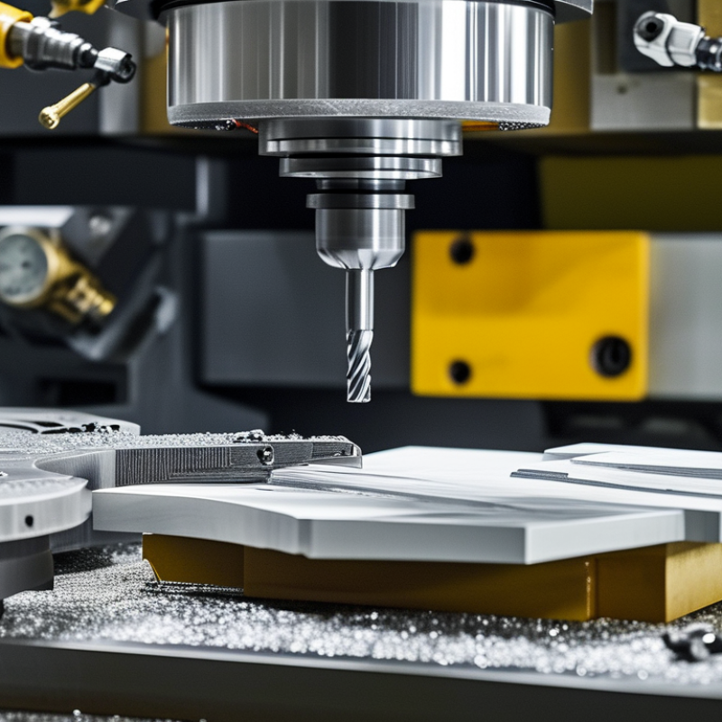
What Is Precision Machining and How Does It Work?
Precision Machining} is the controlled production of components with extremely tight dimensions, repeatable finishes, and dependable performance. It relies on CNC mills, lathes, grinders, cutting tools, inspection systems, and carefully managed process data. A machined part may appear simple, yet a small variation can affect assembly, sealing, movement, or safety.
The process begins with a digital design and suitable material selection. Engineers then choose cutting speeds, feeds, tooling, workholding methods, and inspection points. During machining, the tool removes material in measured steps. Temperature, vibration, tool wear, and machine alignment can still change the result. That reality is often underestimated.
Measurement is central. William Edwards Deming, a leading quality expert, famously said, “You cannot inspect quality into a product.” His statement applies directly to Precision Machining. Quality must develop through stable methods, capable equipment, trained operators, and honest verification. Coordinate measuring machines, micrometers, gauges, and surface testers reveal whether the finished part meets its requirements.
But precision is not perfection. Even advanced equipment has limits. Material movement, thermal expansion, and human decisions remain part of the process. A successful manufacturer therefore studies variation instead of hiding it. That habit improves reliability over time.
This guide explains what precision machining is and how it works. It follows the journey from engineering drawings to finished components. You will see how machines remove material, how tolerances guide decisions, and why inspection cannot replace process control. The details matter. Small errors can become expensive failures. Yet careful planning, practical experience, and disciplined measurement make accurate production achievable.
What Precision Machining Means and Why It Matters
Precision machining means removing material with controlled accuracy. A CNC machine follows digital toolpaths from CAD and CAM software. Cutting tools shape metal, plastic, or composites in measured passes. Inspectors then verify dimensions with micrometers, gauges, or coordinate measuring machines.
The meaning is practical. A shaft that is 0.01 millimeters oversized may jam inside a bearing. A loose hole may create vibration, noise, or early wear. Tolerances, surface finish, material behavior, and thermal expansion must work together. Grand View Research estimated the global CNC machine market exceeded 80 billion dollars in 2023. Deloitte’s 2024 Smart Manufacturing and Operations Survey found that 86% of manufacturing leaders expect smart manufacturing to drive competitiveness within five years. These figures show strong investment. They do not guarantee good parts.
Tips: Define critical dimensions before programming. Match tolerance levels to actual function. Check the first article carefully. Record tool wear and inspection results. Small records prevent large arguments.
Precision machining matters because consistency protects performance, safety, and production schedules. It also reduces scrap when process controls are stable. Still, tighter tolerances are not automatically better. They can increase cycle time, tool wear, and inspection costs. That is where engineering judgment matters. In real workshops, a perfect drawing can meet an imperfect machine, operator, or material batch. Reviewing those gaps honestly improves the process. Precision is not only a small number. It is repeatable control from design through inspection.
The Machines, Tools, and Materials Used in Precision Work
Precision machining turns engineering drawings into tightly controlled parts. CNC mills remove material with rotating cutters. CNC lathes shape round components while the workpiece spins. Electrical discharge machining cuts hardened materials with controlled sparks. Grinding removes tiny amounts and improves surface finish. Each machine follows programmed coordinates, but skilled operators still check tool wear, heat, vibration, and setup errors. A small offset can change a bearing seat or sealing surface. Real production is less perfect than diagrams suggest.
Tool selection depends on the material, geometry, and required finish. Carbide cutters handle many steels and aluminum alloys. Ceramic tools can tolerate higher cutting temperatures, but they may chip under unstable conditions. Stainless steel, titanium, brass, and engineering plastics each behave differently during cutting. Coolant controls heat and helps clear chips. Micrometers, gauges, and coordinate measuring machines verify dimensions after machining. Measurement is not optional; it is evidence that the process worked.
Tips: Secure the workpiece firmly before cutting. Keep cutting edges sharp and replace worn tools early. Check the first part carefully, especially holes, threads, and thin walls. Record temperature and measurement results when tolerances are tight. Experienced machinists also question unusual readings instead of correcting them blindly. Sometimes the inspection method, not the part, creates the problem.
How a Precision Machining Project Moves from Design to Part
A precision machining project begins with a practical design, not just a detailed drawing. Engineers review the CAD model, material, dimensions, surface finishes, and critical tolerances. They also check whether each feature can be reached by cutting tools. A narrow internal corner may look acceptable on screen but create problems during machining. Small design changes can reduce setup time and tool wear.
The machinist then converts the approved design into manufacturing instructions. CAM software creates toolpaths, while experienced programmers select cutting speeds, feeds, tools, and workholding methods. The raw material is secured carefully, because slight movement can affect every measured feature. Machining may involve milling, turning, drilling, or several operations in sequence. The part often returns to the machine more than once.
Inspection takes place during and after production. Operators use calibrated gauges, probes, or coordinate measuring equipment to compare the part with the drawing. A first article can reveal an overlooked tolerance or an unrealistic finish requirement. That is not always a failure; it is useful evidence for revision. Still, rushed feedback can cause expensive rework. Reliable projects keep inspection records, verify material certificates, and document changes. Precision is built through controlled decisions, repeated checks, and honest attention to details that are easy to miss.
The Main Techniques for Achieving Tight Machining Accuracy
Precision machining produces components whose dimensions may differ by only a few micrometres. Tight accuracy begins with a controlled process, not a single machine setting. Engineers study the drawing, material, tolerances, and datum structure before cutting metal. Geometric dimensioning and tolerancing helps define what “accurate” really means. Without clear datums, inspection results can become misleading.
Rigid fixturing is essential. A thin aluminum plate can bend under clamping pressure, then spring back after release. Machinists reduce this risk with balanced supports, suitable clamping force, and careful workholding checks. Tool selection matters as well. A sharp carbide cutter can reduce burrs, heat, and deflection. Cutting speed and feed must match the material, tool condition, and feature geometry. Coolant also controls temperature, although excessive flow can disturb delicate setups. The process needs restraint.
Modern CNC equipment uses probing to locate edges, verify work offsets, and measure selected features during production. Thermal growth still matters, especially during long runs. Operators may allow the machine to stabilize, monitor temperature, and apply compensation when evidence supports it. Final inspection can involve micrometers, air gauges, optical systems, or coordinate measuring machines. Measurement strategy should match the tolerance, not merely the available instrument. A rushed inspection is unreliable. One practical weakness remains: even a carefully planned process can drift when tools wear faster than expected. Recording tool life and checking critical dimensions at defined intervals helps reveal that drift before it becomes a costly batch problem.
What Is Precision Machining and How Does It Work?
Precision machining removes material with tightly controlled cutting, grinding, electrical, or thermal processes. The chart compares representative achievable dimensional tolerances for common techniques; lower values indicate greater machining accuracy.
Actual results depend on the machine, workpiece material, tooling, temperature control, measurement method, and part geometry. Grinding and jig grinding are typically selected when tighter tolerances are required than standard CNC milling or turning can provide.
How Precision Machined Parts Are Inspected and Improved
Precision machining becomes trustworthy when parts are measured, not merely produced. After cutting, inspectors check critical dimensions with calibrated micrometers, gauges, and coordinate measuring machines. They compare actual values with engineering drawings and permitted tolerances. A bore may look smooth yet measure slightly tapered. That difference can affect assembly, sealing, and service life. Small details matter.
Inspection begins with a controlled environment. Temperature, vibration, and cleanliness can influence readings. Inspectors record dimensions, material condition, surface finish, and tool-related marks. For complex parts, a coordinate measuring machine maps several points across each feature. Surface roughness testing reveals machining patterns that touch inspection may miss. Results should remain traceable to the machine, tool, operator, and measurement equipment. This record supports professional decisions rather than guesses.
When a dimension drifts, engineers review cutting speed, feed rate, tool wear, and fixture stability. They may adjust offsets, replace a worn insert, or improve workholding. A repeat measurement confirms whether the change truly worked. No inspection system is perfect. Errors happen. A hurried setup can create false confidence, even with accurate instruments. Experienced teams question unusual results and measure again before releasing parts. A first pass can still mislead us. Reflecting on that weakness helps improve inspection plans, operator training, and process control.
| Category | Machining or Inspection Dimension | Typical Information | How It Supports Accuracy and Quality |
|---|---|---|---|
| Precision Machining Fundamentals | |||
| Definition | Precision machining | Computer-controlled or highly controlled material-removal processes used to produce parts with specified dimensions, tolerances, and surface finishes. | Maintains repeatable geometry and functional fit for components used in mechanical, medical, aerospace, electronics, and industrial applications. |
| Typical equipment | Multi-axis CNC machine tools | Common configurations include 3-axis, 4-axis, and 5-axis machining centers, as well as CNC turning centers. | Additional axes can reduce repositioning, improve access to complex surfaces, and help maintain feature-to-feature relationships. |
| Common materials | Machinable metals and engineering plastics | Examples include aluminum alloys, carbon steel, stainless steel, titanium alloys, brass, copper, acetal, nylon, and PEEK. | Material selection affects cutting forces, thermal expansion, tool wear, surface finish, and achievable tolerance. |
| Primary processes | Milling, turning, drilling, boring, reaming, and grinding | Milling removes material with rotating cutters; turning rotates the workpiece; grinding uses an abrasive wheel for fine finishing. | The process is selected according to part geometry, required tolerance, material, production volume, and surface-finish requirement. |
| Digital preparation | CAD and CAM programming | A 3D CAD model defines the part, while CAM software converts toolpaths into machine instructions such as G-code. | Simulation and toolpath verification help identify collisions, excess stock, gouges, and inefficient cutting movements before production. |
| Workholding | Fixtures, vises, chucks, and soft jaws | The workpiece is located and clamped against defined reference surfaces without excessive distortion. | Stable workholding reduces vibration, movement, setup variation, and errors caused by part deflection. |
| Cutting control | Speed, feed, depth of cut, and coolant | Cutting parameters are adjusted for tool material, workpiece material, tool diameter, rigidity, and the desired finish. | Correct parameters control heat, cutting forces, chip formation, tool wear, and dimensional stability. |
| Typical tolerance range | General CNC dimensional tolerance | Approximately ±0.05 mm to ±0.ของ2 mm is common for many CNC operations; tighter values require suitable equipment, process control, and verification. | Tolerance capability depends on machine condition, material, feature size, temperature, tooling, setup, and drawing requirements. |
| Surface finish | Arithmetic average roughness (Ra) | Many milled or turned surfaces may fall around Ra 1.6–6.3 µm; fine finishing or grinding can achieve lower roughness values. | Surface roughness influences friction, sealing, fatigue performance, appearance, and the function of mating surfaces. |
| Inspection and Measurement | |||
| First-article inspection | Initial part verification | The first completed part, or a defined first-off sample, is measured against the engineering drawing and inspection plan. | Detects programming, setup, tooling, and interpretation errors before a larger quantity is produced. |
| Dimensional inspection | Calipers and micrometers | Calipers provide versatile outside, inside, and depth measurements; micrometers provide higher-resolution measurements for suitable features. | Useful for routine checks of diameters, thicknesses, lengths, steps, and accessible features. |
| Coordinate inspection | Coordinate measuring machine (CMM) | A CMM uses a probing system to measure points in three-dimensional space and compare them with CAD or drawing requirements. | Measures size, location, position, orientation, profile, concentricity, and other geometric characteristics with traceable procedures. |
| Optical inspection | Vision systems and optical comparators | Non-contact systems use cameras, lenses, or projected profiles to inspect small features, contours, angles, and edge conditions. | Reduces the risk of contact damage and supports efficient inspection of delicate or difficult-to-reach features. |
| Surface inspection | Surface roughness measurement | A profilometer traces or scans a surface and reports parameters such as Ra, Rz, or Rt. | Confirms whether the produced finish meets functional or drawing requirements rather than relying only on visual judgment. |
| Thread inspection | Thread plug and ring gauges | Go gauges verify that a thread is within the functional acceptance condition; no-go gauges check that it is not excessively loose. | Provides a fast functional check for internal and external threads in production environments. |
| Form inspection | Roundness, cylindricity, and contour measurement | Specialized instruments or CMM methods evaluate deviations from ideal circular, cylindrical, or contoured geometry. | Identifies errors that may not be detected by measuring only one diameter or one linear dimension. |
| Visual inspection | Surface and workmanship review | Operators check for burrs, scratches, dents, discoloration, tool marks, incomplete edges, contamination, and visible defects. | Confirms basic workmanship and helps prevent cosmetic or handling defects from reaching assembly. |
| Measurement reliability | Calibration and traceability | Inspection equipment should be calibrated at defined intervals against standards traceable to recognized national or international measurement systems. | Improves confidence that reported measurements are accurate, repeatable, and suitable for acceptance decisions. |
| Process Improvement and Corrective Action | |||
| Process capability | Cp and Cpk analysis | Capability indices compare process variation and centering with specification limits; the interpretation depends on the applicable quality requirements. | Shows whether a stable process can consistently meet a tolerance instead of relying only on final inspection. |
| Statistical control | Control charts | Measured values are plotted over time to identify trends, drift, cycles, or unusual variation. | Enables earlier intervention before dimensional results move outside specification limits. |
| Tool management | Tool wear monitoring and replacement | Tool life is controlled using cutting time, part count, measured wear, cutting-load changes, or surface-quality results. | Reduces dimensional drift, burr formation, poor finish, tool breakage, and unexpected process interruptions. |
| Thermal control | Temperature stabilization | Machines, workpieces, cutting tools, and inspection equipment are allowed to stabilize when thermal expansion could affect results. | Improves consistency for close-tolerance features and reduces disagreement between machining and inspection measurements. |
| Root-cause analysis | Corrective and preventive action | Teams investigate sources such as incorrect offsets, fixture movement, tool wear, material variation, vibration, or programming errors. | Addresses the underlying cause of nonconformance and helps prevent the same defect from recurring. |
| Design improvement | Design for manufacturability | Designers may reduce unnecessary tight tolerances, improve tool access, add suitable radii, and define realistic surface-finish requirements. | Can improve manufacturability, reduce cost, shorten cycle time, and increase process robustness without reducing part function. |
| Post-machining improvement | Deburring, cleaning, coating, heat treatment, or grinding | Secondary operations are applied when required by the drawing, material specification, corrosion requirement, hardness requirement, or assembly function. | Improves edge safety, cleanliness, wear resistance, hardness, corrosion resistance, or final dimensional condition. |
| Final release | Inspection report and nonconformance control | Results are documented and compared with approved specifications before parts are accepted, reworked, or rejected. | Creates objective evidence of conformity and supports controlled decisions throughout the production process. |